
Injection molding is the dominant production process for plastic parts at scale. For inventors, entrepreneurs, and small business owners developing plastic products, understanding injection molding is foundational to Phase 2 design and Phase 3 production commitments — tooling is one of the largest capital commitments in physical product development.
Quick Answer
Injection molding injects molten thermoplastic under high pressure into a precision-machined mold, then cools and ejects the finished part. It’s the standard production process for plastic parts at meaningful quantities. Processes range from standard molding through multi-cavity, family molds, insert molding, and overmolding. Materials include ABS, polypropylene, polycarbonate, nylon, and specialty grades. Cost scales with tooling investment, cavity count, material, and quantity. Injection molding fits Phase 3 production at appropriate volumes; CNC machining or soft tooling may fit better at lower volumes.
Key Facts
- Injection molding is the dominant production process for plastic parts — injecting molten thermoplastic into precision molds under high pressure
- Tooling is the largest upfront cost; per-part cost drops significantly with production volume
- Materials include common thermoplastics (ABS, polypropylene, polycarbonate, nylon, PMMA, HDPE) and specialty grades for specific applications
- Processes span standard molding, multi-cavity production, family molds, insert molding, and overmolding — matched to part requirements
- The tooling commitment is a Phase 2 and Phase 3 decision that requires design maturity, validated prototypes, and volume justification before commitment
Key Takeaways
- Injection molding is a volume-driven process; the tooling investment justifies itself through per-part cost reduction at scale
- Design decisions in Phase 2 shape injection molding cost, quality, and manufacturability at Phase 3
- Material selection at Phase 2 should specify the production material — prototype testing should use production-equivalent materials
- Cost drivers include tooling complexity, cavity count, material, part geometry, tolerances, surface finish, and quantity
- Different mold types fit different production volumes: prototype tooling for low volume, soft tooling for bridge production, hardened steel for full production
- Committing to injection molding tooling before design is validated is one of the most expensive Phase 2→Phase 3 mistakes inventors make
Table of Contents
- What Injection Molding Is and How It Differs from Other Production Methods
- Injection Molding Processes for Product Designers
- Materials You Can Injection Mold
- Tolerances, Surface Finishes, and Geometry Considerations
- What Drives Injection Molding Cost
- When Injection Molding Fits and When Other Methods Fit Better
- Injection Molding in the Four-Phase Product Development Sequence
- How Rabbit Product Design Approaches Injection Molding for Inventor Projects
What Injection Molding Is and How It Differs from Other Production Methods
Injection molding injects molten thermoplastic under high pressure into a precision-machined mold cavity, cools it, and ejects the finished part. Cycle times from seconds to a couple of minutes make it cost-effective at scale. Tooling investment is significant, but once amortized across production quantity, per-part cost is low.
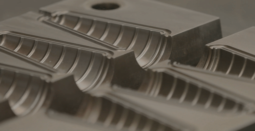
The mold is the core of the process — a precision-machined steel or aluminum tool with cavities defining part geometry, cooling channels regulating temperature, runners and gates directing molten material, and ejection systems releasing the finished part. Modern molds can include hot runners for faster cycle times. The mold is expensive to make and modify, which is why disciplined design and prototyping before tooling commitment matters.
Compared to CNC machining, injection molding has much higher tooling investment but much lower per-part cost at volume. Compared to soft tooling, hardened steel injection molding produces parts at lower per-part cost with longer tool life but higher upfront investment. Injection molding fits high-volume plastic production where tooling investment amortizes.
Injection Molding Processes for Product Designers
Standard injection molding. The most common process. Molten thermoplastic injects into a single or multi-cavity mold, cools, and ejects. Handles most plastic parts — housings, structural components, mechanical parts, consumer product bodies. Cavity count determines parts per cycle: single-cavity for low volumes or complex parts; multi-cavity for higher volumes where per-part cost matters most.
Family molds. A family mold produces multiple different parts in a single cycle — useful when a product assembly includes parts produced in similar quantities. Family molds share tooling infrastructure, reducing total tooling cost. The trade-off is that parts produce at the same rate, so imbalanced demand creates inventory challenges.
Insert molding. Insert molding places a preformed component (metal insert, threaded bushing) into the mold before injection so the injected plastic captures it. Fits parts requiring metal threads, electrical contacts, or structural reinforcement. Eliminates secondary assembly by producing the assembled part directly.
Overmolding. Overmolding injects a second material over a previously molded substrate — typically a rigid base with a soft-touch elastomer overmold for grip surfaces, ergonomic pads, or waterproof seals. Fits products combining rigid and flexible characteristics.
Gas-assist and structural foam molding. Specialty processes injecting gas or foaming agents alongside the thermoplastic to produce lightweight parts with hollow sections or foam cores. Specialized processes for specific applications.
Process selection for product designers. Process selection follows from part requirements. Standard parts with straightforward geometry use standard injection molding with cavity count appropriate to volume. Parts requiring integrated components use insert molding. Multi-material requirements use overmolding. Multi-part assemblies with matched quantities use family molds. Most consumer parts use standard injection molding; specialty processes come in when the part specifically requires them.
Materials You Can Injection Mold
Injection molding handles a wide range of thermoplastic materials with different mechanical properties, cost, and processing requirements. Material selection at Phase 2 specifies the production material; prototype testing in the same material produces production-equivalent behavior.
ABS (acrylonitrile butadiene styrene). The workhorse material for consumer product housings. Good mechanical strength, impact resistance, machinability for prototypes, moderate cost. Used for enclosures and structural parts where balanced mechanical properties matter.
Polypropylene (PP). Chemically resistant, low-density, flexible with good fatigue resistance. Used for living hinges, containers, chemical-resistant applications, and packaging. Cheap and easy to process but with lower mechanical strength than ABS.
Polycarbonate (PC). High impact strength, optical transparency in clear grades, good thermal stability. Used for impact-resistant enclosures, optical parts, and safety equipment. Costs more than ABS but delivers better impact resistance and thermal capability.
Nylon (polyamide, PA6 and PA66). Excellent mechanical strength, wear resistance, and chemical resistance. Used for gears, structural components, and mechanical assemblies. Absorbs moisture, affecting properties in service — important for humid environments.
Acrylic (PMMA). Optical transparency, weather resistance, hard scratch-resistant surface. Used for lenses, light guides, and display covers. More brittle than polycarbonate but with better optical clarity.
HDPE and LDPE (polyethylene). Chemically resistant, low cost, flexible in low-density grades. Used for containers, closures, packaging, and consumer components where chemical resistance and low cost matter.
Engineering thermoplastics. Higher-performance materials: POM (acetal, Delrin) for precision mechanical parts, PEEK for high-temperature applications, PPS for demanding thermal environments, and filled grades (glass-filled, carbon-filled) for additional strength. Cost more than commodity plastics; the right choice when the application requires them.
Material specification for production. Material specification at Phase 2 should specify the exact production material — grade, additives, colorants. Prototype testing in the specified material produces production-equivalent behavior. Substituting easier materials leaves risk gaps that surface at Phase 3.
Tolerances, Surface Finishes, and Geometry Considerations
Injection molding produces parts at the dimensional accuracy and surface finish the design specifies, within the process limits. Understanding what injection molding can achieve informs disciplined Phase 2 design.
Dimensional tolerances. General injection molding tolerances suit most consumer product applications. Precision tolerances are achievable through careful tooling design and process control but require additional investment. Specify tolerances appropriate to functional requirements; over-specifying adds cost without benefit.
Wall thickness. Wall thickness is one of the most consequential decisions. Uniform wall thickness produces consistent cooling and reduces warpage, sink marks, and dimensional variation. Thick sections cool slowly, producing sink marks or voids; thin sections may not fill completely. Design around a nominal thickness appropriate to the material and part size.
Draft angles. Draft angles — slight tapers on vertical surfaces — are required for parts to eject cleanly. Insufficient draft produces parts that stick in the mold. Standard draft angles are typically 1-2 degrees on most surfaces; deeper features may require more. Draft angle design is a Phase 2 decision.
Gate and parting line placement. The gate is where molten material enters the cavity; the parting line is where mold halves separate. Gate location affects fill patterns, weld lines, and surface aesthetics. Parting line placement affects visible seams and secondary finishing. Both should be considered during Phase 2 design rather than left to the tooling shop.
Ribs and bosses. Ribs add stiffness without adding wall thickness. Bosses provide mounting points. Rib thickness is typically 50-60% of adjacent wall thickness to avoid sink marks; bosses need appropriate wall ratios and draft. Disciplined Phase 2 design addresses these details.
Surface finish. Surface finishes range from high-polish mirror through matte textured to as-machined. Mold surface finish transfers directly to the part. Textured finishes hide small defects; polished finishes reveal every imperfection. Specify finish appropriately for functional and aesthetic requirements.
What Drives Injection Molding Cost
Injection molding cost splits into tooling investment (one-time) and per-part cost (recurring). Understanding both categories informs Phase 2 design that produces cost-effective production.
Tooling investment. The mold is the largest single upfront cost, driven by mold size, cavity count, steel grade, complexity (slides, lifters, ejection), surface finish, and expected tool life. Aluminum prototype tooling costs significantly less than hardened steel but has shorter tool life; the choice depends on volume.
Material cost. Material cost per part depends on the thermoplastic grade and part weight. Commodity materials cost less than engineering plastics. Hot runner systems reduce material waste versus cold runners but require additional tooling investment.
Cycle time. Cycle time directly affects per-part cost by determining parts per machine hour. It’s affected by part geometry (thick walls cool slower), material selection, and tooling design (efficient cooling channels reduce time). Design decisions reducing cycle time reduce per-part cost across the run.
Cavity count. Adding cavities produces more parts per cycle, reducing per-part cost at scale. Multi-cavity tooling costs more upfront but produces multiple parts per cycle. The break-even depends on volume: single-cavity for lower volumes; multi-cavity for higher. Cavity count should be based on realistic volume projections.
Volume amortization. Per-part cost drops significantly as volume increases because tooling amortizes across more parts. Injection molding is cost-effective at high volume; other methods amortize better at low volume.
Secondary operations. Secondary operations — trimming, assembly, decoration, packaging — add cost beyond molding. Designs minimizing them (via insert molding, overmolding, in-mold decoration) can reduce total cost.
When Injection Molding Fits and When Other Methods Fit Better
Injection molding isn’t the right production method for every plastic part. Different methods serve different volume, complexity, and material profiles.
When injection molding fits. Production volumes high enough to amortize tooling. Parts require consistent dimensional accuracy and repeatable production. Consumer products at retail volumes, hardware components at scale, and plastic parts where production quality at volume is the objective.
When CNC machining fits better. Low-volume production where tooling isn’t justified. Parts requiring frequent design iteration. Prototype validation in production-grade materials before tooling commits. Small production runs of specialty hardware.
When soft tooling fits better. Bridge production between prototype validation and hard tooling. Low-to-moderate volumes where hard tooling isn’t yet justified. Soft tooling (aluminum or urethane molds) produces injection-molded parts at lower tool life but much lower tooling cost — a common bridge for first-time inventor products.
The soft tooling to hard tooling transition. A common Phase 3 sequence uses soft tooling for initial production to validate the injection molding process and market response, then transitions to hardened steel once volume justifies the investment. This reduces the risk of committing hard tooling before validation.
Method selection during Phase 2. Phase 2 design should identify the production method and design for it. Designs optimized for CNC don’t always translate cleanly to injection molding; injection-molding designs may not machine efficiently. Making the method decision during Phase 2 produces designs suited to the method.
Injection Molding in the Four-Phase Product Development Sequence
Injection molding fits within the four-phase sequence at specific points, with Phase 2 design decisions shaping Phase 3 production.
Phase 1 (Research & Ideation). Injection molding doesn’t drive Phase 1 directly, but Phase 1 informs Phase 2. Market volume projections inform whether tooling investment will amortize. Unit economics includes tooling cost against per-unit savings. Regulatory pathway analysis identifies material or process requirements shaping Phase 2.
Phase 2 (Design & Prototype): Design for injection molding. Phase 2 design for injection-molded parts includes injection-molding-specific DFM: wall thickness uniformity, draft angles, rib and boss design, gate and parting line planning, appropriate tolerance specifications. Designs made without process consideration often require Phase 3 rework.
Phase 2 (Design & Prototype): Prototype validation. Before committing to tooling, disciplined Phase 2 work validates the design through prototyping in production-equivalent materials. CNC machined prototypes in the production thermoplastic behave like production parts under mechanical, thermal, and fit testing. Soft-tooled samples validate the injection molding process itself before hard tooling commits.
Phase 3 (Sourcing & Manufacturing): Tooling and production. Phase 3 includes tooling design, fabrication, debug, first-article inspection, and production runs. Tooling debug cycles the mold and adjusts process parameters. First-article inspection validates the tooling produces parts within specification. Production then runs at scale.
Phase 3: Quality control. Ongoing quality control monitors output through in-process sampling and periodic inspection.
Phase 4 (Branding & Marketing). Injection molded parts contribute to the product experience — quality perception, brand impression, unboxing. Molded parts themselves are Phase 3 output; presentation is Phase 4.
How Rabbit Product Design Approaches Injection Molding for Inventor Projects
Rabbit Product Design is a product development firm built around inventors, entrepreneurs, and small business owners who carry the most risk on a first physical product. The firm has 9 years in business, over 2,000 products developed, and senior engineers averaging 27 years of experience.
Injection molding spans Phase 2 and Phase 3. Phase 2 design embeds injection molding DFM — wall thickness, draft, rib and boss design, gate and parting line planning. Phase 2 prototyping uses CNC machining in production thermoplastic and soft tooling for injection-molded samples, validating design and process before hard tooling. Phase 3 covers tooling design coordination, fabrication oversight, debug, first-article inspection, and quality control.
The five verticals — consumer products, soft goods (bags, cases, wearables, sports gear, pet products), hardware (brackets, hinges, latches, mounting systems, mechanical assemblies, fixtures, storage hardware), electronic products and IoT, and inventor projects — include many products with injection-molded parts. Consumer products often have injection-molded housings; hardware includes injection-molded mechanical components; electronic products use injection-molded enclosures.
On the cost question first-time inventors weigh: injection molding tooling is one of the largest capital commitments in physical product development. Committing it against an unvalidated design is one of the most expensive Phase 3 mistakes. Senior engineers catch design issues at Phase 2 where correction is cheap. The total cost of an engagement with Rabbit Product Design is lower when injection molding tooling gets built against a properly validated design — even when the per-hour rate is higher than junior alternatives — because the cascading cost of tooling built against inadequate design is avoided.
Injection Molding Services Across Phases
- Phase 2: injection-molding DFM (wall thickness, draft, ribs, gates, parting lines)
- Phase 2: prototyping via CNC machining and soft tooling to validate design before tooling commits
- Phase 3: tooling design coordination with production factories
- Phase 3: tooling fabrication oversight, debug, first-article inspection
- Phase 3: production quality control
To begin a product development engagement with structured injection molding design and Phase 3 execution, contact Rabbit Product Design.
Conclusion
Injection molding is the dominant production process for plastic parts at scale — tooling investment is the largest upfront cost; per-part cost drops with volume. Processes span standard molding, family molds, insert molding, and overmolding. Materials include ABS, polypropylene, polycarbonate, nylon, PMMA, HDPE, and engineering plastics. Wall thickness, draft angles, gate placement, tolerances, and surface finishes are Phase 2 decisions shaping Phase 3 cost and quality. Injection molding fits high-volume production; CNC and soft tooling fit lower volumes. Understanding injection molding as a Phase 3 commitment shaped by Phase 2 decisions is foundational to disciplined product development.
FAQ
How do I know when my design is ready for injection molding tooling?
Design readiness requires validated Phase 2 work: mechanical function confirmed through prototype testing in production-equivalent materials, fit validated at production tolerances, injection-molding DFM applied, material specification finalized, and a stable design. Committing tooling before validation is one of the most expensive Phase 3 mistakes.
What’s the difference between soft tooling and hard tooling for injection molding?
Soft tooling uses aluminum or urethane molds for low-to-moderate volumes; hard tooling uses hardened steel for high volume. Soft tooling costs significantly less upfront but has shorter tool life. Many inventor projects use soft tooling for initial production before transitioning to hard tooling once volume justifies the investment.
How many cavities should my injection mold have?
Cavity count depends on production volume projections. Single-cavity is more cost-effective for lower volumes. Multi-cavity tooling (2, 4, 8, 16, or more) costs more upfront but produces multiple parts per cycle. The decision should be based on realistic volume projections rather than defaults.
Can I use CNC machining for prototypes and then move to injection molding for production?
Yes — one of the most common Phase 2→Phase 3 patterns. CNC machined prototypes in the production thermoplastic validate the design in production-equivalent behavior before committing tooling. Phase 2 design should consider injection molding requirements so it translates cleanly to tooling.
What happens if the injection molding tooling produces defective parts?
First-article inspection at Phase 3 catches tooling problems before full production commits. If inspection reveals defects, corrective action follows: tooling rework, process adjustment, material substitution, or design modification depending on root cause. Re-inspection validates the correction before production resumes. Catching tooling problems at FAI is much cheaper than discovering them after full production.
Sources
- Rabbit Product Design
- Fictiv — Design for Manufacturing (DFM): A Guide to Developing Products Efficiently
Keywords: injection molding, injection molding for product designers, plastic manufacturing, injection molding materials, injection molding tooling, injection molding cost
