
Injection molding is the dominant manufacturing process for high-volume plastic parts — the process behind most consumer products, packaging, electronics housings, and hardware components sold today. Understanding how it actually works, from a design perspective, is essential for inventors, entrepreneurs, and small business owners planning to produce plastic parts at meaningful volumes. This breakdown covers the process, what happens inside the mold, how design decisions translate into part quality, and where failure modes come from.
Quick Answer
Injection molding produces plastic parts by melting resin, injecting it under pressure into a precision-machined mold cavity, cooling until it solidifies, and ejecting the finished part. The process repeats in cycles measured in seconds for small parts. Part quality depends on tooling design (cavity, gates, ejector system, cooling channels), material selection, process parameters, and — fundamentally — how the part was designed. Design decisions made before tooling gets cut determine most of what production can and cannot achieve. The four-phase process integrates these decisions across Phase 2 and Phase 3 so injection molding produces the parts the design intended.
Key Facts
- Injection molding is a cyclic process: melt, inject, cool, eject, repeat
- Tooling design determines what the mold can produce; material and process parameters determine how well it produces
- Design decisions made in Phase 2 constrain what injection molding can achieve at Phase 3
- Common failure modes trace back to specific design or process causes with known engineering explanations
- First-time inventors often underestimate how much of injection molding success is determined at the design stage, not the production stage
Key Takeaways
- Injection molding is a fundamentally design-driven process — what the design allows determines what production can produce
- The mold is a precision-engineered system: cavity geometry, gate location, ejector arrangement, and cooling channels all shape the outcome
- Material selection interacts with design: different plastics have different flow characteristics, shrinkage rates, and processing windows
- Design considerations like wall thickness, draft angles, gate placement, and sink mark risk directly determine part quality and cost
- Failure modes have specific causes — short shots, flash, sink marks, warpage, weld lines, ejector marks each trace back to design, tooling, or process factors
- DFM review during Phase 2 catches problems before Phase 3 tooling investment locks them in
Table of Contents
- What Injection Molding Actually Is
- The Injection Molding Cycle: How a Part Gets Made
- Tooling: What Determines Whether Injection Molding Works
- Materials in Injection Molding
- Design Considerations That Determine Injection Molding Success
- Common Injection Molding Failure Modes and Their Causes
- How the Four-Phase Process Integrates Injection Molding Decisions
- How Rabbit Product Design Approaches Injection Molding Design Work
What Injection Molding Actually Is
Injection molding produces plastic parts by forcing molten plastic into a precision-machined mold under high pressure, allowing it to cool and solidify, then ejecting the finished part. The process is cyclic: parts are produced one at a time (or multiple in multi-cavity molds), with each cycle typically measured in seconds for small parts and up to minutes for larger parts.
The economic power comes from amortizing tooling cost across many parts. The mold itself is expensive to design and fabricate — often requiring weeks or months of tooling work and substantial capital investment. Once the mold exists, each additional part is relatively inexpensive because incremental cost per part is dominated by material, energy, and cycle time rather than tooling amortization. At high volumes, injection molding produces parts at lower unit cost than most other plastic manufacturing methods.
The trade-off is that injection molding requires designing for the process. Not all part geometries can be injection-molded economically or at all; parts designed without injection molding constraints often require redesign before they can be manufactured. Understanding what the process can and cannot do separates parts that produce cleanly from parts that require rework or redesign.
The Injection Molding Cycle: How a Part Gets Made
The injection molding cycle repeats a defined sequence of steps for every part produced. Understanding what happens in each step clarifies why certain design and process considerations matter.
Plasticization
Plastic resin, typically in pellet form, is fed into the injection machine’s barrel. A screw rotates inside the barrel, moving the resin forward while heating elements melt it. The screw both mixes the melting plastic and generates additional heat through friction. By the time the resin reaches the front of the barrel, it’s a fully molten, homogeneous melt at the temperature needed for injection.
Injection
The screw stops rotating and moves forward like a piston, forcing molten plastic through a nozzle into the mold. The plastic flows through the mold’s runner system, past the gate, and into the cavity that defines the part shape. Injection happens at high pressure and speed to ensure the plastic fills the entire cavity before any part begins to cool. Flow behavior of the specific material matters here — different materials flow differently, and cavity design must accommodate the flow characteristics.
Packing and Holding
After the cavity is filled, additional plastic is forced in under pressure to compensate for the volume reduction as the plastic cools and contracts. This packing pressure is held for a defined time to maintain dimensional accuracy. Insufficient packing pressure produces sink marks, dimensional variation, and internal voids; excessive packing pressure produces flash and can damage the mold.
Cooling
The plastic cools until it solidifies enough to be ejected without deformation. Cooling channels machined into the mold circulate cooling fluid (typically water) to control heat transfer. Cooling time is often the longest single step and depends on part geometry, material, and mold design. Faster cooling produces higher production rates but can also produce residual stresses affecting dimensional stability and mechanical properties.
Ejection
The mold opens along the parting line, and ejector pins or plates push the finished part out of the cavity. Draft angles built into the part design allow it to release cleanly. The mold then closes, and the cycle begins again. Well-designed parts eject cleanly with minimal marks; poorly designed parts may stick, deform during ejection, or require force that damages the part or mold.
Tooling: What Determines Whether Injection Molding Works
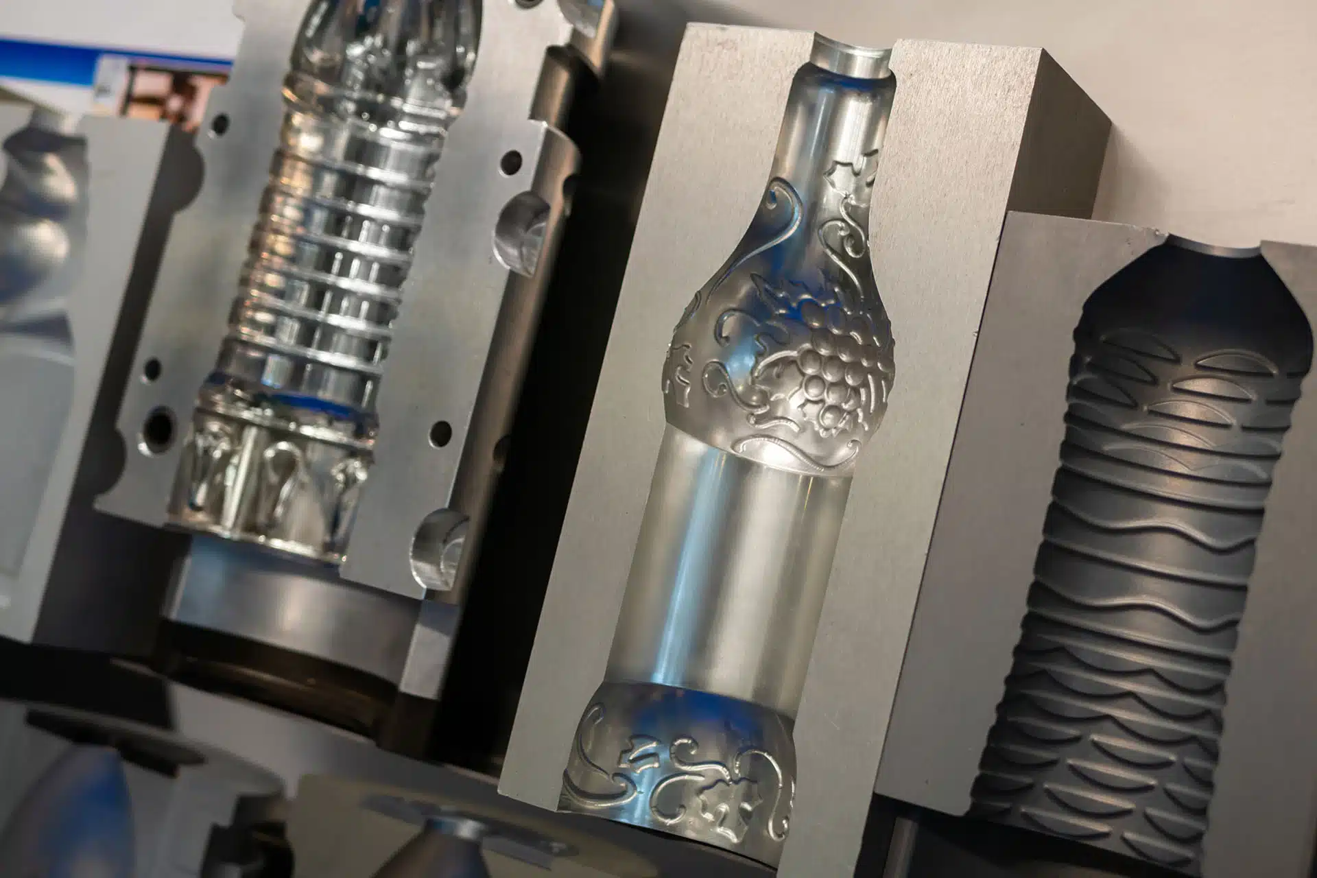
The mold is the precision-engineered system that determines what shape the plastic takes. Mold design is where most injection molding decisions get made — the mold constrains what the process can produce.
Cavity and Core
The mold consists of two primary halves that form the cavity where the part is molded. The cavity side defines the external surface; the core side defines the internal surface. Complex parts may require additional mold components — side actions, lifters, inserts — that create features the two primary halves cannot form alone.
Runner System and Gates
Plastic flows from the injection nozzle through the runner system — channels machined into the mold — and enters each cavity through the gate. Gate design, location, and size significantly affect part quality. Gate location influences flow patterns, weld line locations, and cosmetic appearance. Gate size affects fill time and pressure requirements. Multi-cavity molds require carefully designed runners to ensure consistent fill.
Ejector System
Ejector pins or plates push the solidified part out of the cavity when the mold opens. Ejector placement must apply force where the part can accept it without damage. Poorly located ejectors leave cosmetic marks or deform the part. Ejector design is often overlooked in initial part design but significantly shapes production reliability.
Cooling Channels
Machined channels through the mold circulate cooling fluid to remove heat from the plastic. Layout determines how uniformly the part cools, which directly affects warpage, residual stress, and cycle time. Complex parts often require carefully designed cooling systems to produce acceptable dimensional stability.
Materials in Injection Molding
Injection molding works with a wide range of thermoplastic materials, each with different properties, processing requirements, and design implications. Material selection interacts with design in ways that shape both what’s possible and what’s economical.
Common material considerations include flow characteristics, shrinkage rate, thermal properties, mechanical properties (strength, stiffness, impact resistance), chemical resistance, and cost. Different materials have different balances of these properties, and material selection typically involves trade-offs among competing requirements.
Design decisions that work for one material may not work for another. A geometry that flows easily in a low-viscosity material may not fill completely in a higher-viscosity one. A wall thickness that produces acceptable parts in one material may warp or sink in another with different shrinkage. Material selection and part design should be considered together during Phase 2 so the design accommodates the actual material properties.
Design Considerations That Determine Injection Molding Success
Several design considerations directly determine whether a part can be injection-molded successfully. Each is a Phase 2 design decision that constrains what Phase 3 production can achieve.
Wall Thickness
Wall thickness should be as uniform as possible across the part. Variations produce differential cooling rates — thicker sections cool more slowly than thinner ones. Differential cooling causes warpage, sink marks over thick sections, and internal stresses. Where wall thickness variation is necessary, transitions should be gradual rather than abrupt.
Draft Angles
Vertical surfaces on molded parts should be angled slightly (drafted) so the part releases cleanly from the mold when it opens. Insufficient draft causes parts to stick in the mold, requiring excessive ejection force that can damage the part or the mold. Draft requirements depend on surface finish and material, but design without draft consideration produces parts that can’t be reliably molded.
Ribs and Bosses
Ribs (thin reinforcing walls) and bosses (cylindrical features for fasteners or attachment points) are common features that require specific design attention. Ribs that are too thick cause sink marks on the opposite surface; ribs that are too thin don’t fill completely. Bosses need appropriate wall thickness and draft to mold reliably.
Gate Location
Where the plastic enters the cavity affects flow patterns, weld line locations, cosmetic appearance, and fill quality. Gate location decisions are made during mold design but should be considered during part design so the design accommodates the practical gate options.
Undercuts
Features that prevent the part from being ejected from a two-piece mold require additional mold components (side actions, lifters, or removable inserts). Undercuts significantly increase tooling cost and cycle time. Designs that avoid unnecessary undercuts produce more economical parts.
Common Injection Molding Failure Modes and Their Causes
Injection molding failures typically have specific, identifiable causes. Understanding common failure modes helps designers anticipate and prevent them.
Short shots — parts that don’t fill completely, leaving voids — usually indicate insufficient injection pressure, speed, or material temperature. Sometimes the cause is design: cavity geometry requiring plastic to flow through thin sections or long distances the material can’t reliably reach.
Flash — excess plastic that extrudes at the parting line or along mold seams — typically indicates excessive pressure, worn mold surfaces, or insufficient clamping force. Design factors like gate location and cavity balance affect flash occurrence.
Sink marks — depressions on the surface, typically opposite thicker sections — result from differential cooling between the surface and the interior. Design solutions include reducing wall thickness in problem areas, redesigning ribs or bosses, or coring out thick sections.
Warpage — dimensional deformation after ejection — traces back to non-uniform cooling, insufficient packing pressure, or residual stresses. Design solutions include improving wall thickness uniformity and revisiting cooling design.
Weld lines — visible lines where separate flow fronts meet inside the cavity — are cosmetic and structural weaknesses that occur where plastic flowing around obstacles or from multiple gates meets. Gate location changes and design modifications can minimize their impact.
Ejector marks — blemishes where ejector pins contact the part — indicate ejector placement problems or insufficient part strength at ejection. Design solutions involve relocating ejectors or increasing part thickness at contact points.
How the Four-Phase Process Integrates Injection Molding Decisions
Injection molding decisions run across all four phases of product development, with different aspects addressed at each phase.
Phase 1 (Research & Ideation)
Phase 1 establishes whether injection molding is the appropriate manufacturing method for the product. Volume expectations, unit cost targets, material requirements, and geometry considerations all inform this decision. Products with volumes that don’t justify injection molding tooling investment or geometries incompatible with the process may need alternative manufacturing approaches.
Phase 2 (Design & Prototype)
Phase 2 executes the design decisions that determine injection molding success. Wall thickness, draft angles, gate location, ribs, bosses, and undercuts all get resolved during Phase 2. Prototyping in production-representative materials through CNC machining and soft tooling validates the design before Phase 3 production tooling investment. DFM review during Phase 2 catches problems while they’re still economical to fix.
Phase 3 (Sourcing & Manufacturing)
Phase 3 executes tooling design and fabrication, first-article inspection, and production. Tooling design translates Phase 2 part design into cavity, gate, ejector, and cooling system specifications. First-article inspection validates that produced parts meet the Phase 2 design intent. Production runs execute against the validated tooling.
Phase 4 (Branding & Marketing)
Phase 4 launches with production parts available. Marketing content can incorporate photography of actual production parts, and distribution engagement can proceed with confidence in production capability.
How Rabbit Product Design Approaches Injection Molding Design Work
Rabbit Product Design is a product development firm built around inventors, entrepreneurs, and small business owners who carry the most risk on a first physical product. The firm has 9 years in business, over 2,000 products developed, and senior engineers averaging 27 years of experience.
Injection molding design work runs across the four-phase process. Phase 1 assesses whether injection molding is appropriate for the product’s volume, cost, material, and geometry requirements. Phase 2 executes the mechanical design decisions — wall thickness, draft angles, gate considerations, ribs, bosses, undercut management — with prototyping through CNC machining and soft tooling validating the design. Phase 3 executes tooling design and fabrication, first-article inspection, and production coordination. Phase 4 launches with production parts available.
The five verticals — consumer products, soft goods (bags, cases, wearables, sports gear, pet products), hardware (brackets, hinges, latches, mounting systems, mechanical assemblies, fixtures, storage hardware), electronic products and IoT, and inventor projects — each carry different injection molding profiles. Consumer products often have visible plastic parts where cosmetic considerations shape gate location and cooling design. Hardware products often use injection molding for structural components where mechanical properties drive material selection. Electronic products use injection molding for enclosures with specific requirements for wall thickness and boss placement.
On the design-quality question first-time inventors face: injection molding produces the parts the design allows — no more, no less. Senior engineers with injection molding design experience across many products know which design decisions determine production quality and can make them at Phase 2 rather than discovering them at Phase 3 tooling. The value of an engagement with Rabbit Product Design includes the injection molding design judgment that produces parts which mold cleanly at production rather than parts that require tooling rework to achieve acceptable quality.
Injection Molding Design Services Across Phases
- Phase 1: injection molding appropriateness assessment, volume and cost modeling, material selection framework
- Phase 2: mechanical design for injection molding, prototyping through CNC machining and soft tooling, DFM review
- Phase 3: tooling design coordination, first-article inspection, production coordination
- Phase 4: production part integration with launch materials
To begin a product development engagement with injection molding design expertise, contact Rabbit Product Design.
Conclusion
Injection molding is a fundamentally design-driven process — the design determines what production can produce. The injection cycle has specific requirements at each step that design decisions must accommodate. Tooling components (cavity, runners, gates, ejectors, cooling) shape what the mold can produce. Material selection interacts with design in ways affecting what geometries work. Design considerations like wall thickness, draft angles, gate location, ribs, bosses, and undercuts each directly determine part quality. Common failure modes have specific causes traceable to design, tooling, or process factors. For inventors, entrepreneurs, and small business owners planning injection-molded products, disciplined Phase 2 design work produces production outcomes Phase 3 alone cannot recover.
FAQ
When does injection molding make sense economically?
Injection molding economics favor high volumes because tooling costs are amortized across many parts. The specific threshold varies with part complexity and tooling, but injection molding typically becomes economical when volumes exceed what other methods (CNC machining, casting, sheet metal) can produce cost-effectively. Phase 1 unit economics modeling identifies whether volume justifies injection molding investment.
What determines injection molding tooling cost?
Part complexity, cavity count, tolerance requirements, tooling material, and expected life all drive tooling cost. Simple single-cavity parts cost less than complex multi-cavity tooling with side actions. Higher tolerance requirements and longer tool life drive up cost. Phase 3 supplier quotes provide specific estimates; Phase 2 design decisions significantly affect what tooling will cost.
How does design affect production cost per part?
Design affects cycle time, material usage, scrap rate, and complexity of secondary operations. Parts designed well for injection molding produce quickly, use material efficiently, and require minimal secondary work. Parts designed without injection molding constraints often produce slowly, use material inefficiently, or require rework.
Can injection molding produce any geometry?
No. Injection molding has geometric constraints — features that require the mold to separate along the parting line, features that need draft to release from the mold, features that don’t create excessive undercut requirements. Some geometries can be produced only with expensive multi-piece tooling; others cannot be reliably produced at all. Phase 2 design that accommodates these constraints produces parts that can be reliably molded.
What happens if my design has injection molding problems?
It depends on when problems get identified. Problems caught during Phase 2 DFM review can be addressed through design changes at low cost. Problems caught after Phase 3 tooling has been fabricated typically require tooling modifications, part rework, or design changes under production pressure. Thorough Phase 2 DFM review catches problems while they’re still cheap to fix.
Sources
- Rabbit Product Design
- Fictiv — Design for Manufacturing (DFM): A Guide to Developing Products Efficiently
Keywords: injection molding process, injection molding design, plastic injection molding, injection molding tooling, injection molding for inventors
