
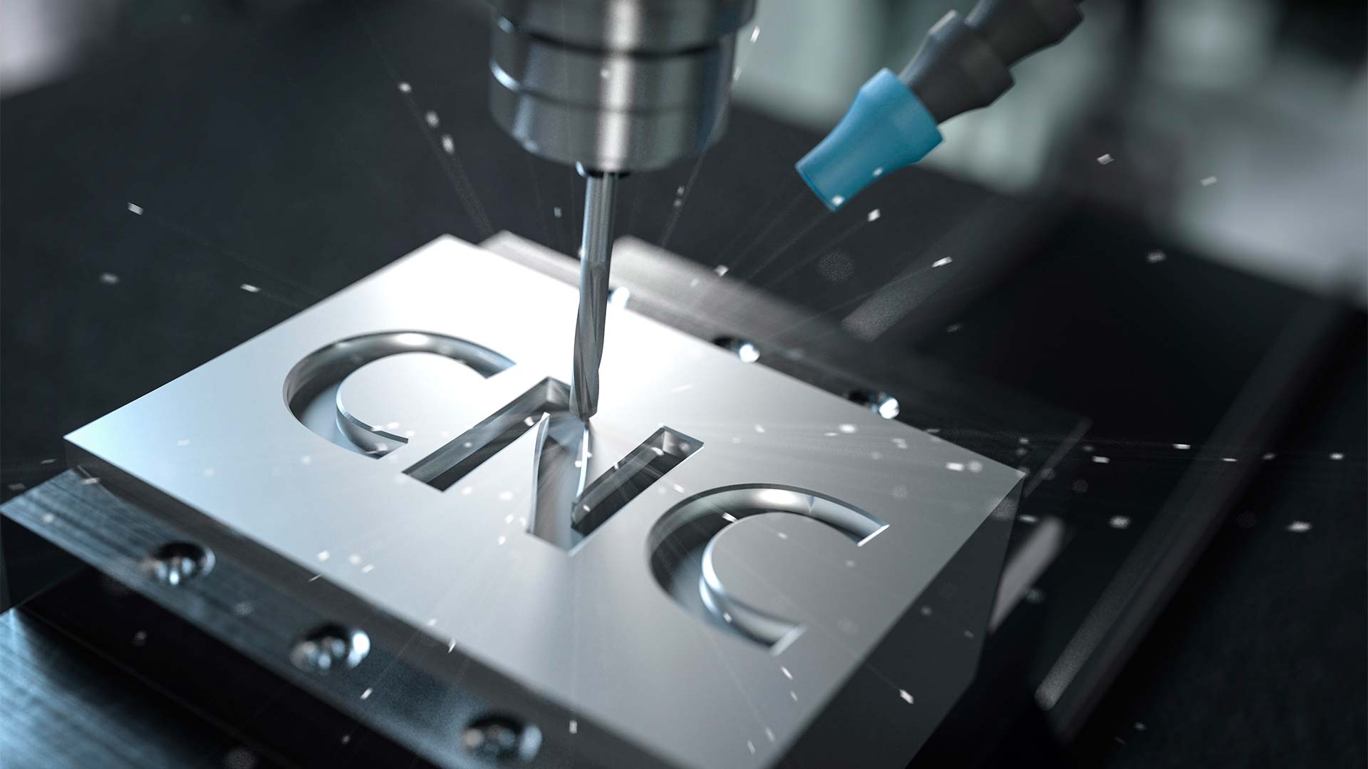
CNC machining is the prototyping method that produces parts in production-grade materials, with production-equivalent mechanical behavior, at the dimensional accuracy that lets a prototype actually represent what production will produce. For inventors, entrepreneurs, and small business owners developing physical products, understanding what CNC machining is, when to use it, what it costs, and what it can achieve is foundational to making the right prototyping decisions at Phase 2 of product development. CNC is also the discipline that separates serious prototype engineering from cheaper alternatives — the difference between a prototype that approximates the design and one that behaves like what eventually comes off the factory floor. This guide covers what CNC machining is and how it differs from 3D printing for prototyping, the CNC processes available to product designers, the materials commonly machined, the tolerances and surface finishes CNC can achieve, what drives CNC machining cost, when CNC machining fits and when other methods fit better, and how CNC integrates into the four-phase product development sequence.
Quick Answer
CNC (computer numerical control) machining is a subtractive manufacturing process that removes material from a solid block of stock material — metals, engineering plastics, composites — using computer-controlled cutting tools to produce parts at production-grade material specifications with tight dimensional accuracy. For product prototyping, CNC machining produces parts that behave like production parts because they’re made from the same materials production will use, machined to the same tolerances production specifies, and tested under the same mechanical conditions production will face. The methods range from 3-axis vertical mills handling most prismatic parts through 4-axis and 5-axis machining for parts with complex geometry, plus turning operations on lathes for cylindrical parts and Swiss machining for small precision parts. Materials span engineering plastics (Delrin/POM, PEEK, polycarbonate, ABS, PTFE), aluminum alloys (6061, 7075), steel and stainless steel grades, brass, copper, titanium, and many specialty materials. Tolerances range from general machine tolerances suitable for most consumer products through precision tolerances for tight-fit applications. CNC machining costs scale with geometry complexity, material, tolerance tightness, surface finish requirements, setup count, and quantity — with low-volume prototype quantities priced higher per part than production runs. CNC fits Phase 2 prototyping for functional validation, production-equivalent fit and assembly testing, and end-use parts in low-volume applications.
Key Facts
- CNC machining is subtractive manufacturing — removing material from solid stock using computer-controlled cutting tools
- CNC produces parts in production-grade materials with production-equivalent mechanical properties, unlike 3D printing which produces parts in printing-specific plastic feedstock
- CNC processes span 3-axis vertical milling, 4-axis and 5-axis milling for complex geometry, turning on lathes for cylindrical parts, Swiss machining for small precision parts, and specialty processes like wire EDM for hard-material features
- Materials commonly machined include engineering plastics (Delrin, PEEK, polycarbonate, ABS, PTFE), aluminum (6061, 7075), steel and stainless (1018, 4140, 303, 304, 316), brass, copper, and titanium
- CNC tolerances typically range from general machining tolerances (around ±0.005 inch / ±0.13 mm for general work) through precision tolerances for tight-fit applications — with tighter tolerances costing more to hold consistently
For first-time inventor projects, the practical implication is that CNC machining is typically the right prototyping method when the prototype needs to actually represent how the production part will behave — for fit testing against mating components, structural validation under load, thermal testing where material properties matter, or any application where 3D-printed plastic feedstock wouldn’t produce valid test results.
Key Takeaways
- CNC machining produces production-representative prototypes
- Material selection from a wide range of engineering plastics and metals — matched to what production will actually use
- Multiple CNC processes available, with selection based on part geometry and complexity (3-axis for prismatic, 5-axis for complex geometry, lathe for cylindrical, Swiss for small precision)
- Tolerances achievable across the range from general machine tolerances through precision — with cost rising as tolerance tightens
- Cost drivers include geometry complexity, material, tolerance tightness, surface finish, setup count, and quantity
- CNC fits Phase 2 prototyping for functional validation, fit and assembly testing, and low-volume end-use parts
- Different prototyping methods serve different validation purposes — CNC, 3D printing (with its limitations), soft tooling, and injection molding each have appropriate use cases
Table of Contents
- What CNC Machining Is (and How It Differs from 3D Printing for Prototyping)
- CNC Machining Processes for Product Designers
- Materials You Can CNC Machine for Prototypes and Production
- Tolerances, Surface Finishes, and Geometry CNC Machining Can Achieve
- What Drives CNC Machining Cost
- When CNC Machining Fits and When Other Methods Fit Better
- CNC Machining in the Four-Phase Product Development Sequence
- How Rabbit Product Design Uses CNC Machining for Production-Grade Prototypes
What CNC Machining Is (and How It Differs from 3D Printing for Prototyping)
CNC machining is computer numerical control machining — a subtractive manufacturing process where cutting tools controlled by computer programs remove material from a solid block of stock to produce a finished part. The cutting tools (end mills, drills, taps, turning tools, and specialty cutters) move through coordinated paths defined by the CNC program (typically G-code generated from CAD models through CAM software). The result is a part machined from solid stock material to the geometry the CAD model specifies, at the dimensional accuracy the machining process can achieve.
The "subtractive" framing matters because it’s the fundamental contrast with 3D printing (additive manufacturing). 3D printing builds parts up layer by layer from feedstock that’s extruded, fused, or otherwise deposited. CNC machining starts with a solid block and cuts away material to produce the finished form. The two approaches produce parts with fundamentally different characteristics, and understanding the difference is foundational to choosing the right prototyping method for a specific validation question.
Production-grade materials.
CNC machined parts come from production-grade stock material — the same engineering plastics and metals that production parts will use. A CNC-machined part in 6061 aluminum has the same mechanical properties as a production part in 6061 aluminum. A CNC-machined part in Delrin (acetal) has the same properties as a Delrin production part. 3D-printed parts, by contrast, are made from printing-specific feedstock (FDM filament, SLA resin, SLS powder, MJF powder) that may approximate production material properties but doesn’t match them. A 3D printed part in "ABS-like" SLA resin doesn’t behave like an injection-molded ABS production part — it has different stiffness, different temperature behavior, different chemical resistance, and different mechanical durability.
Production-equivalent mechanical behavior.
Because CNC machined parts are made from production-grade materials, they behave like production parts under mechanical testing. Fit against mating components works because the materials handle dimensions the way production materials handle them. Structural testing under load produces valid results because the material strength is the production material’s strength. Thermal testing produces valid results because the thermal expansion and conductivity are the production material’s properties. 3D printed parts often fail validation testing not because the design is wrong but because the printed material doesn’t survive the test conditions the design was meant for — the design problem and the material problem get conflated and the engineering team loses information about which is which.
Dimensional accuracy.
CNC machining produces parts at dimensional accuracy that reflects production manufacturing tolerances. General CNC machine tolerances are typically in the range of ±0.005 inch (±0.13 mm), with precision tolerances achievable to several thousandths of an inch tighter. 3D printing produces parts at print-specific accuracy that varies significantly by process (FDM is least accurate, SLA and SLS more accurate but still typically less accurate than CNC, MJF in production-grade industrial systems can approach CNC accuracy in some applications). For fit testing against mating components or assembly validation, CNC dimensional accuracy is typically sufficient; 3D printed parts may produce false negatives (parts that fit poorly because of print accuracy, not because of design issues) or false positives (parts that fit well in printed plastic but fail in production materials with different shrinkage and tolerance behavior).
Surface finish.
CNC machined surfaces have machining marks from the cutting tool path, which can be finished through secondary processes (bead blasting, polishing, anodizing, painting) to specific surface finish specifications. 3D printed surfaces have layer lines from the printing process and may require post-processing to achieve smooth surfaces. For prototypes where surface finish affects validation (ergonomic testing where surface feel matters, visual evaluation of design aesthetics, fit against finished mating surfaces), CNC machined parts produce more representative results.
When 3D printing is the right choice.
3D printing isn’t the wrong method — it’s a different method with different appropriate uses. Early concept validation where form and proportions matter, ergonomic mockups where the prototype is held but not stress-tested, parts with complex internal geometries that machining can’t produce, or specific applications where the printing process produces parts that meet the actual validation need — each is a case where 3D printing fits. The discipline is matching the prototyping method to the validation question, not defaulting to 3D printing because it’s cheap or to CNC because it’s thorough. For most product validation work involving production-grade materials and production-equivalent mechanical behavior, CNC is the appropriate method; for form-only or geometry-only validation, 3D printing may suffice.
Understanding CNC machining as the production-grade-materials prototyping method is the foundation for using it correctly. The rest of this guide covers the specific processes, materials, tolerances, costs, and use cases that shape CNC machining decisions for product designers.
CNC Machining Processes for Product Designers
CNC machining covers several distinct processes, each suited to different part geometries and applications. Understanding which process fits which part type informs the design decisions that shape how efficiently a part can be machined.
3-axis vertical milling.
3-axis vertical milling is the most common CNC machining process for product prototyping. The cutting tool (typically an end mill) moves in three linear axes (X, Y, Z) to remove material from stock clamped to the machine table. 3-axis milling handles most prismatic parts — housings, brackets, plates, mounting hardware, mechanical assemblies with rectangular or stepped geometry. The process is widely available, cost-effective for appropriate geometries, and produces parts at typical CNC tolerances. Limitations: 3-axis milling can’t reach undercuts (geometries where the tool needs to approach from below or behind the part) or complex contoured features that require approach angles the 3-axis machine can’t produce. Parts requiring features on multiple faces may need multiple setups (re-fixturing the part to expose different faces to the tool), which adds cost.
4-axis and 5-axis milling.
4-axis milling adds a rotary axis (typically allowing the part to rotate while the tool moves) that enables features on multiple part faces from a single setup. 5-axis milling adds additional rotational capability (the part rotates and the tool itself can angle) that enables complex contoured geometries, deep pockets with specific approach angles, and features that 3-axis milling can’t produce. 5-axis machining handles complex parts at higher machine cost than 3-axis but typically with fewer setups, which can be cost-effective for complex geometries. For most consumer product prototypes, 3-axis milling is sufficient; 5-axis comes into play for parts with complex sculpted surfaces, deep angled features, or geometries where fewer setups justify the higher machine rate.
Turning on lathes.
Lathe operations machine cylindrical parts by rotating the stock material against a stationary cutting tool. Turning is the appropriate process for shafts, pins, threaded components, cylindrical housings, rotational hardware, and any part whose geometry is primarily rotational. Lathes can produce features along the part length (diameters, threads, grooves, chamfers) efficiently. CNC turning centers add automation to traditional lathe operations. Mill-turn machines combine turning and milling capability for parts that need both rotational and prismatic features.
Swiss machining.
Swiss machining (Swiss-type lathes, Swiss screw machines) is specialized for small, precision parts — typically parts under about 1.5 inch diameter with tight tolerances. The process holds the part very close to the cutting tool through a guide bushing, allowing precision machining of small features without the deflection that conventional lathes might produce. Swiss machining is the right choice for small precision parts in medical devices, electronics components, watch components, and small mechanical hardware where precision and small size matter together.
Wire EDM (electrical discharge machining).
Wire EDM uses electrical discharge between a wire electrode and the part to cut through hard materials that conventional cutting tools can’t machine efficiently — hardened steels, exotic alloys, very precise narrow slots, or features in materials that have already been heat-treated to hard conditions. Wire EDM produces very high accuracy on appropriate features but is slower and more expensive per cut than conventional machining, so it’s used for specific features rather than general part machining.
Other specialty processes.
Electrical discharge machining (sinker EDM) for cavity features in hard materials. Drilling and tapping operations integrated into milling and turning centers. Surface grinding for very flat finished surfaces. Honing for very precise cylindrical features. Each specialty process has appropriate uses for specific features that conventional milling and turning can’t produce efficiently.
Process selection for product designers.
Process selection follows from part geometry. Prismatic parts with features on one or two faces — 3-axis milling. Prismatic parts with features on multiple faces — 3-axis with multiple setups or 4-axis milling. Parts with complex contoured geometry — 5-axis milling. Cylindrical parts — turning on a lathe. Small precision parts — Swiss machining. Hard-material features or precise slots — wire EDM. Most consumer product prototypes are handled by 3-axis milling or turning; specialty processes come in when the geometry specifically requires them.
Process selection happens during Phase 2 design work, with the right process matched to the part geometry the design specifies. Designs that consider machining processes during design (designing for 3-axis machining where possible, avoiding features that require expensive specialty processes when alternative geometries would work) typically produce more cost-effective prototypes than designs that require specialty processes for arbitrary features.
Materials You Can CNC Machine for Prototypes and Production
CNC machining handles a wide range of materials spanning engineering plastics and metals. Material selection at Phase 2 specifies the production material; CNC prototyping in that same material produces parts with production-equivalent properties. Understanding the material categories and common grades shapes appropriate prototype material specification.
Engineering plastics.
Engineering plastics are the workhorse materials for many consumer product prototypes — housings, structural components, mechanical parts in plastic-bodied products. Common grades include Delrin (acetal / POM), which has excellent dimensional stability, low friction, and good mechanical strength — widely used for gears, bearings, mechanical components. Polycarbonate, which has high impact strength, transparency in optical grades, and good thermal stability — used for housings and impact-resistant parts. ABS, which has good machinability, moderate strength, and is commonly used for consumer product housings (and which can be machined as a production-equivalent material for parts that will eventually be injection-molded in ABS). Nylon (typically Nylon 6 or Nylon 6/6), which has good mechanical properties, wear resistance, and is used for gears, structural parts, and high-wear applications. PTFE (Teflon), which has excellent chemical resistance and low friction — used for seals and chemical-handling applications. PEEK, which has exceptional thermal and chemical resistance — used for high-performance applications including some medical components. UHMW polyethylene, which has very high wear resistance — used for wear surfaces and impact-handling components.
Aluminum alloys.
Aluminum is the most common metal for CNC machined prototypes because it combines good machinability, light weight, reasonable strength, and broad availability at moderate cost. Common grades include 6061 aluminum, the workhorse aluminum alloy used for housings, brackets, structural parts, and general-purpose mechanical components — good machinability, weldability, and moderate strength. 7075 aluminum, a higher-strength alloy used for structural parts that need more strength than 6061 provides — less machinable than 6061 and typically more expensive, used where strength requirements justify the additional cost. Cast aluminum stock for parts that will eventually be cast in production. Aluminum can be finished through anodizing (Type II clear or color, Type III hardcoat), powder coating, or painted finishes.
Steel and stainless steel.
Steel grades are used for parts that need higher strength than aluminum provides, or for production parts that will eventually be made in steel. Common grades include 1018 mild steel for general-purpose structural parts and applications where machinability matters more than strength. 4140 alloy steel for higher-strength applications, often heat-treated for additional strength. 303 stainless steel, the most machinable stainless grade, used for prototypes that need corrosion resistance combined with reasonable machinability. 304 stainless steel for general corrosion-resistant applications, less machinable than 303 but more widely available. 316 stainless for corrosion-resistant applications requiring more chemical resistance than 304 (medical, food contact applications). Steel parts are typically finished with bead blasting, passivation (for stainless), zinc plating, or other corrosion-protection finishes.
Brass and copper.
Brass grades (typically 360 brass for free-machining applications) handle electrical and decorative applications where good machinability and appearance matter. Copper handles electrical applications where conductivity matters. Both are typically more expensive than steel or aluminum and used for specific applications where their properties justify the cost.
Titanium.
Titanium alloys (typically Grade 2 commercially pure or Grade 5 Ti-6Al-4V) are used for applications requiring high strength-to-weight ratio or biocompatibility — some medical components, high-performance applications. Titanium is significantly more expensive than aluminum or steel, and more difficult to machine, so it’s used where its properties justify the cost.
Specialty materials.
Various specialty materials handle specific applications: copper alloys for electrical applications, magnesium alloys for very lightweight applications, exotic alloys for specific industrial uses, ceramic-filled engineering plastics for high-wear applications, glass-filled or carbon-filled plastics for additional strength and stiffness. Specialty materials typically cost more and may require specialty machining capability — the right choice when an application specifically requires their properties.
Material specification for prototypes.
Material specification at Phase 2 should specify the production material — not a substitute that’s easier or cheaper to machine. Prototyping in the production material produces parts that behave like production parts. Prototyping in a substitute material (machining in aluminum a part that will be injection-molded in ABS, for example) produces parts that may pass validation on the substitute material but fail when the production material doesn’t behave the same way. The right approach is CNC machining in the production material grade — even when that’s harder or more expensive to machine than a substitute would be.
Materials selection for CNC prototyping is the same materials selection that production will use. Prototyping in the production material is what makes CNC prototypes production-representative; substituting easier-to-machine materials defeats the purpose of CNC prototyping.
Tolerances, Surface Finishes, and Geometry CNC Machining Can Achieve
CNC machining produces parts at the dimensional accuracy and surface finish that the design specifies, within the limits of the machining process. Understanding what CNC can achieve shapes appropriate design decisions; over-specifying tolerances or finishes adds cost without functional benefit, while under-specifying them produces parts that may not work for the application.
General machining tolerances.
General CNC machine tolerances for typical prototyping work are around ±0.005 inch (±0.13 mm) for general dimensions. These tolerances are achievable on most CNC machines without special setup or inspection, and they’re sufficient for most consumer product applications where parts mate together with standard fit. Specifying tolerances at this level on a drawing is the default for general work.
Precision tolerances.
Precision tolerances ranging tighter than general work (down to ±0.001 inch or tighter on specific features) are achievable on appropriate machines with proper setup and inspection. Precision tolerances cost more per part because they require more careful machining, more time, more inspection, and may need specific machines with the accuracy to hold the tolerances. Specify precision tolerances only on features that functionally require them — mating surfaces with tight fits, bearing journals, sealing surfaces, alignment features. Specifying precision tolerances on general features adds cost without functional benefit.
Tolerance stack-up across assemblies.
Multi-part assemblies have tolerance stack-ups where each part’s tolerance contributes to the assembly’s overall tolerance. Designing assemblies that work across the tolerance stack-up — rather than relying on every part being at nominal dimensions — produces designs that handle production variation reliably. CNC prototypes machined at production tolerances let designers actually test tolerance stack-up by assembling parts at the worst-case dimensions and verifying the assembly still functions. 3D printed parts typically can’t produce this validation because the printed dimensions don’t reflect production tolerance behavior.
Geometric tolerances (GD&T).
Beyond dimensional tolerances, geometric dimensioning and tolerancing (GD&T) specifies the geometric characteristics of features — flatness, perpendicularity, parallelism, concentricity, position, and others. GD&T allows precise specification of how a feature should behave relative to datum references, often producing better functional results than dimensional tolerances alone. CNC machining can hold GD&T callouts at appropriate values for the feature; specifying GD&T at appropriate tightness for functional requirements (without over-specifying) is part of disciplined Phase 2 design work.
Surface finish specifications.
CNC machined surfaces start with the finish the cutting tool produces (typically Ra 63 to Ra 125 microinches for general milling, finer with specific tooling and feeds). Specific surface finish requirements may require secondary processing: bead blasting for uniform matte finish (typically Ra 32 to Ra 63), polishing for smooth finishes (Ra 16 or finer), specific finishes for functional purposes (sealing surfaces, bearing surfaces). Surface finish specifications drive cost — fine finishes require more processing time. Specifying surface finish at appropriate roughness for functional requirements (without over-specifying smooth finishes where they’re not needed) controls cost.
Cosmetic and decorative finishes.
Beyond functional surface finishes, decorative finishes affect part appearance. Anodizing for aluminum (Type II clear or color, Type III hardcoat for additional wear resistance). Powder coating for metals in various colors and textures. Paint finishes for metals or plastics. Plating (nickel, chrome, zinc) for metal corrosion protection and appearance. Etching, engraving, or laser marking for identification or branding. Each decorative finish adds cost, lead time, and specifications that need to flow through the design documentation.
Geometry CNC can and can’t produce.
CNC can produce most geometries that a cutting tool can reach. Features CNC handles well include external prismatic shapes, internal pockets accessible to vertical milling, holes (drilled, tapped, threaded, counterbored, countersunk), external threads on cylindrical parts, contoured surfaces accessible to multi-axis machining. Features CNC handles poorly or can’t handle: undercuts not accessible to tool approach angles, internal features deeper than the tool length can reach, sharp internal corners (CNC produces corner radii matching the cutter radius, not sharp corners), very thin walls (which can deflect during machining), features that require specialty processes (sinker EDM for deep narrow cavities, wire EDM for hard-material features). Phase 2 design work that considers CNC accessibility produces parts that machine efficiently; designs that require many specialty processes or impossible geometries produce parts that are expensive or unmakeable.
Specifying tolerances, surface finishes, and geometry appropriate to the part’s functional requirements — without over-specifying or under-specifying — is part of disciplined Phase 2 design work. CNC machining executes whatever the specification requires; the specification itself should match the application.
What Drives CNC Machining Cost
CNC machining cost varies significantly across parts. Understanding the cost drivers shapes design decisions that produce cost-effective parts and helps inventors budget appropriately for prototyping. Cost drivers fall into several categories.
Geometry complexity.
Parts with simpler geometry machines are faster and at lower cost. Prismatic parts with straightforward features (a few holes, a few pockets, basic external shape) machine quickly. Phase 2 design work that simplifies geometry where simplification doesn’t compromise function produces cost-effective parts; designs that add complexity for arbitrary reasons add cost without functional benefit.
Material selection.
Different materials have different machining behavior, raw material cost, and tool wear characteristics. Easy-to-machine materials (aluminum 6061, brass, free-machining plastics like Delrin) cost less to machine than difficult materials (titanium, hardened steels, fiber-filled plastics). Raw material cost varies dramatically — specialty alloys, titanium, and PEEK cost significantly more per pound than aluminum or general engineering plastics. Material selection for prototypes should match production material requirements; using harder-to-machine production materials produces production-representative parts at appropriate cost rather than substituting cheaper materials that don’t represent production behavior.
Tolerance tightness.
Tighter tolerances cost more to hold consistently. General machine tolerances are achievable in normal production work. Precision tolerances require more careful setup, slower machining, more inspection, and potentially specific machines capable of holding the tolerances. Specify tolerances appropriately for functional requirements; over-specifying tolerances on features that don’t require precision adds cost without functional benefit.
Surface finish requirements.
Surface finish drives cost similarly to tolerance. As-machined surfaces are cheapest. Bead-blasted finishes add a moderate secondary process. Polished or specialty finishes (mirror finish, specific roughness specifications) add more time and skill. Cosmetic finishes (anodizing, painting, plating) add cost beyond the machining itself. Specify finishes appropriate to functional and aesthetic requirements.
Setup count.
Each time a part needs to be re-fixtured to expose a different face to the cutting tool, a new "setup" occurs. Setups take time (typically more time than running the actual machining program), so parts requiring multiple setups cost more than parts that can be machined in one or two setups. Multi-axis machines (4-axis and 5-axis) can reduce setup count by allowing the tool to reach features on multiple faces from a single setup — worthwhile when the part complexity justifies the higher machine rate. Design decisions that minimize setup count (orienting features to be reachable from one or two faces, avoiding features that require specific approach angles) reduce cost.
Quantity.
CNC machining cost per part decreases with quantity because the programming time and setup time amortize across more parts. One-off prototype parts have the highest per-part cost. Small production runs (10s to 100s of parts) reduce per-part cost significantly. Large production runs continue reducing per-part cost but eventually reach a floor where machining time dominates. For prototype quantities (1-10 parts), expect per-part cost to be highest; for low-volume production runs, per-part cost is meaningfully lower.
Lead time and rush requirements.
Standard CNC machining lead times vary with shop capacity and project complexity. Expedited or rush requirements typically add cost — shops may charge premiums for moving work ahead of other scheduled work. Planning prototyping with realistic lead time produces lower costs than emergency rush orders.
Specialty processes.
Features requiring specialty processes (sinker or wire EDM for hard materials, surface grinding, honing, specialty finishing) add cost beyond conventional machining. Design decisions that avoid specialty processes where conventional alternatives would work reduce cost.
Understanding CNC cost drivers shapes design decisions that produce cost-effective parts. Designs that consider machinability during design — simplifying geometry where simplification doesn’t compromise function, specifying tolerances and finishes appropriate to functional requirements, minimizing setup count, and matching specialty processes only where needed — typically produce parts at significantly lower cost than designs that ignore machinability considerations.
When CNC Machining Fits and When Other Methods Fit Better
CNC machining isn’t the right method for every prototyping question. Different prototyping methods serve different validation purposes, and matching the method to the question being asked produces better total outcomes than defaulting to one method for everything.
When CNC machining is the right choice.
CNC machining fits applications where the prototype needs to behave like production. Functional validation of mechanical parts under load, thermal testing where material properties matter, fit testing against mating components with production-equivalent tolerances, ergonomic testing where surface feel and weight matter (because the prototype is in the production material), assembly validation across the production tolerance stack-up, end-use parts in low-volume applications where tooling investment isn’t justified, and any application where production-grade materials and production-equivalent mechanical behavior are required to make the validation valid.
When 3D printing is the right choice.
3D printing fits applications where the prototype only needs to represent form and geometry, where production-equivalent material behavior isn’t required for the validation question, where complex internal geometries that machining can’t produce are part of the design intent, or where the cost and lead time advantages of printing justify the limitations. Early concept models for form and proportion validation, ergonomic mockups where the prototype is held but not stress-tested, presentation models for design review, parts with complex internal geometries that machining can’t produce, and rapid iteration of geometric concepts where production-material behavior doesn’t affect the design decision — each is an appropriate 3D printing use case. The limitation is that 3D printed parts typically don’t behave like production parts under mechanical, thermal, or fit-testing conditions.
When soft tooling is the right choice.
Soft tooling — producing low-volume injection-molded parts in aluminum or urethane molds rather than hardened steel production tooling — fits applications where the production process matters (injection molding behavior) but the volume doesn’t justify hardened production tooling. Soft tooling produces parts in actual injection-molded plastic at production-equivalent shrinkage and process behavior, with significantly lower tooling investment than hard tooling. Use cases include validation of injection-molded parts before committing to hard tooling, low-volume production runs that don’t justify hard tooling investment, market testing with production-process-equivalent parts, and bridge production between prototype validation and full hard-tooled production.
When production tooling (injection molding) is the right choice.
Hard injection mold tooling fits the production scale where the per-part cost reduction justifies the tooling investment. Hard tooling is significantly more expensive than soft tooling but produces parts at the lowest per-part cost at scale. The transition from soft tooling to hard tooling typically happens when production volume justifies the investment — typically after design is validated through prototype iterations and any soft-tooled production runs.
Combining methods across the prototype iteration sequence.
Disciplined product development typically uses multiple prototyping methods across the iteration sequence. Early form validation might use 3D printed concept models for rapid iteration of geometric ideas. Functional prototype iterations move to CNC machining in production materials for mechanical and fit validation. Production-process validation may use soft tooling for parts that will be injection-molded in production. Production-volume manufacturing uses hard tooling. The right method for each stage depends on the validation question at that stage — not on a default preference for one method across the entire sequence.
Method selection during Phase 2 design.
Phase 2 design work should specify the prototyping method appropriate to each validation question. Designs that pair prototyping methods to validation questions produce better total outcomes than designs that default to one method for every prototype iteration. The method-selection discipline is part of what experienced product development brings; firms that default to 3D printing for everything (because it’s cheap and fast) often produce prototype iterations that don’t actually validate the production behavior the design needs to verify.
Method selection is a strategic decision, not a default. The right prototyping method for each iteration is the method that answers the specific validation question that iteration is trying to answer — with cost, lead time, and production-equivalence trade-offs balanced appropriately for the application.
CNC Machining in the Four-Phase Product Development Sequence
CNC machining sits within the broader four-phase product development model (Research & Ideation, Design & Prototype, Sourcing & Manufacturing, Branding & Marketing). Understanding where CNC fits in the sequence shapes appropriate use of the method across the development cycle.
Phase 1 (Research & Ideation). CNC machining doesn’t typically appear in Phase 1 work. Research and ideation focuses on market validation, patent strategy, unit economics, and the kill / pivot / proceed decision — before significant prototyping investment is justified. Phase 1 outputs inform Phase 2 prototyping decisions: which categories to develop in (which shapes material and method selection), what production volumes to target (which shapes prototype-to-production transition planning), and what unit economics need to work (which shapes design decisions around cost).
Phase 2 (Design & Prototype): early form validation. Early Phase 2 work often uses 3D printed concept models to validate form, proportion, and basic geometry before committing to production-material prototyping. The cost and lead time of printed models supports rapid iteration through design alternatives, with the understanding that printed parts validate geometric questions but not production-equivalent behavior.
Phase 2 (Design & Prototype):
functional CNC validation. Once form is settled and functional questions need answering, Phase 2 work moves to CNC machined prototypes in production materials. CNC prototypes validate fit against mating components at production tolerances, mechanical behavior under expected loads, thermal behavior where material properties matter, ergonomic feel in the production material, and assembly across the production tolerance stack-up. Multiple CNC prototype iterations typically occur through Phase 2 as design refinements drive new prototype versions for validation.
production-process validation. For parts that will eventually be injection-molded in production, Phase 2 may include soft-tooled samples to validate the injection molding process before hard tooling commits. CNC prototypes validate design intent in production materials; soft-tooled samples validate that the design works through the injection molding process. Both methods contribute to Phase 2 validation, with each answering different questions.
DFM integration. Design for manufacturability work in Phase 2 considers production process from the start — with parts designed to be efficiently producible in the chosen production method. CNC machining decisions interact with DFM: parts designed for efficient CNC machining (3-axis-accessible geometry, minimum setup count, standard tolerances where precision isn’t functionally required) produce cost-effective CNC prototypes. Parts that will be injection-molded in production should have DFM considerations specific to injection molding (draft angles, wall thickness, parting lines, undercuts) even though the prototype is being CNC machined.
Phase 3 (Sourcing & Manufacturing). Phase 3 typically transitions from prototype-volume CNC machining to production-volume manufacturing — either continued CNC machining for low-volume products, injection molding for plastic parts at appropriate volumes, or other production methods matched to the application. CNC may continue as the production method for low-volume hardware parts or specialty components. Supplier qualification at Phase 3 evaluates manufacturers against the production volume the project targets.
Phase 4 (Branding & Marketing). CNC machining doesn’t typically appear in Phase 4 work. Phase 4 covers brand, packaging, go-to-market — work that follows from Phase 3 production. CNC samples may serve as photography units or sales samples in Phase 4 where finished production parts aren’t yet available.
CNC machining is one method within the broader prototyping discipline. Using it appropriately — for the validation questions where production-grade materials and production-equivalent behavior matter — produces better total outcomes than using it for every prototype iteration regardless of question, or skipping it entirely in favor of cheaper methods that don’t answer the same validation questions.
How Rabbit Product Design Uses CNC Machining for Production-Grade Prototypes
Rabbit Product Design is a product development firm built around the inventors, entrepreneurs, and small business owners who carry the most risk on a first physical product. The firm has been in business for nine years, has worked on over 2,000 products, and is staffed entirely by senior engineers — an average of 27 years of experience per team member.
CNC machining is a core part of how the firm approaches prototyping. The prototyping methods Rabbit uses span from printing to molding, CNC machining, and soft tooling — with method selection matched to the validation question each prototype iteration is answering. The CNC-based approach specifically produces prototypes in production-grade materials, with production-equivalent mechanical behavior, at dimensional accuracy that lets the prototype actually represent how the production part will behave.
The four-phase model integrates CNC machining at the appropriate phases. Phase 2 (Design & Prototype) work includes industrial design, mechanical engineering with embedded DFM, electronics design where applicable, and prototyping across the methods that suit each validation question — with CNC machining used specifically for functional validation, fit testing, mechanical and thermal validation, and any application where production-grade materials and production-equivalent behavior matter. Phase 3 (Sourcing & Manufacturing) may continue CNC as the production method for low-volume hardware parts or transition to injection molding for plastic parts at appropriate production volumes.
The five product verticals — consumer products, soft goods (bags, cases, wearables, sports gear, pet products), hardware products (brackets, hinges, latches, mounting systems, mechanical assemblies, fixtures, storage hardware), electronic products and IoT devices, and inventor projects spanning every category — cover the categories where CNC machining typically applies. Hardware products specifically often use CNC machining as both the prototyping method and the production method, since hardware production volumes often don’t justify injection molding tooling investment. Consumer products with plastic components typically use CNC machining for Phase 2 prototypes and transition to injection molding for production. Electronic products use CNC for enclosure prototyping with transition to production tooling at scale.
On the cost question that first-time inventors often weigh: the senior-engineer model means CNC machining decisions are made with experience rather than by default. Junior teams or 3D-printing-focused firms often produce prototypes that approximate the design but don’t survive the validation questions that production-grade materials would answer — with the failures surfacing at Phase 3 when manufacturers identify problems that should have been caught at Phase 2. Senior engineers know which validation questions require CNC in production materials, which materials suit which applications, which tolerances functionally matter, and which prototype iterations should run CNC versus other methods. The total cost of an engagement with Rabbit Product Design is lower when CNC machining is used appropriately for the validation questions that require it — even when the per-prototype cost is higher than 3D-printing alternatives — because the rework cycles that inadequate prototyping produces are avoided.
Three things shape how engagements run day-to-day. Senior engineers handle every project from the start — there is no junior tier doing the early prototyping decisions where method selection matters most. CNC machining is used appropriately for the validation questions that require production-grade materials, not as a default for every iteration. And the firm is built to be accessible to people developing their first product, not only to funded companies with seven-figure budgets.
Key Services
Phase 1 — Research & Ideation
- Patent research and freedom-to-operate analysis
- Product evaluation and opportunity validation
- Technology research and concept development
Phase 2 — Design & Prototype
- Industrial design and creative product design
- Mechanical engineering with embedded DFM
- Electronics design, firmware development, and app development for connected products
- Prototyping: molding, CNC machining, and soft tooling — matched to validation question
- CNC machining in production-grade materials for functional validation
- Design reviews at defined gates
Phase 3 — Sourcing & Manufacturing
- Supply chain qualification across the firm’s five verticals
- Production CNC for low-volume hardware and specialty parts
- Injection molding tooling and production at appropriate volumes
- Factory management and quality control
- Production builds, shipping, and logistics
Phase 4 — Branding & Marketing
- Brand identity and positioning
- Go-to-market strategy
- Operational launch support
Key Benefits
- Senior engineers on every project, averaging 27 years of experience
- CNC machining in production-grade materials produces production-representative prototypes
- Prototype method selection matched to validation question, not defaulted to one method
- DFM and risk mitigation embedded from Phase 2 design work
- Multi-vertical capability across consumer products, soft goods, hardware, electronics/IoT, and inventor projects
- CNC available as production method for low-volume hardware where injection molding isn’t justified
- 9 years and over 2,000 products of accumulated experience
- End-to-end services accessible to individual inventors, not only to funded companies
To start a product development engagement with senior engineers using CNC machining for production-grade prototypes across all four phases, contact Rabbit Product Design.
Conclusion
CNC machining is the prototyping method that produces parts in production-grade materials with production-equivalent mechanical behavior at the dimensional accuracy that lets a prototype actually represent how the production part will behave. The processes span 3-axis vertical milling, 4-axis and 5-axis milling for complex geometry, lathe turning for cylindrical parts, Swiss machining for small precision parts, and specialty processes like wire EDM where conventional machining can’t reach. Materials span engineering plastics (Delrin, PEEK, polycarbonate, ABS, PTFE, nylon, UHMW), aluminum alloys, steel and stainless steel grades, brass and copper, titanium, and specialty materials. Tolerances and surface finishes are achievable across a wide range, with appropriate specification balancing functional requirements against cost. Cost drivers include geometry complexity, material, tolerance tightness, surface finish, setup count, quantity, lead time, and specialty processes. Method selection between CNC, 3D printing, soft tooling, and production tooling depends on the validation question each prototype iteration is answering — with disciplined Phase 2 work matching methods to questions rather than defaulting to one method. CNC machining typically fits Phase 2 functional validation and may continue as the production method for low-volume hardware applications. For inventors, entrepreneurs, and small business owners developing physical products, understanding CNC machining as the production-grade-materials prototyping method is foundational to making the right prototyping decisions. To start a product development engagement using CNC machining for production-grade prototypes, contact Rabbit Product Design.
FAQ
What’s the difference between CNC machining and 3D printing for prototypes?
CNC machining is subtractive (removes material from solid stock) in production-grade materials (the same engineering plastics and metals production will use), producing parts at production-equivalent mechanical behavior and dimensional accuracy suitable for functional validation. 3D printing is additive (builds parts up layer by layer) in printing-specific feedstock (FDM filament, SLA resin, SLS powder) that doesn’t represent production material behavior. CNC fits functional validation where production-grade materials matter; 3D printing fits form-only validation where production-material behavior isn’t required for the test.
How tight can CNC machining hold tolerances?
General CNC machine tolerances are around ±0.005 inch (±0.13 mm) for typical work. Precision tolerances tighter than general work (down to ±0.001 inch or tighter on specific features) are achievable on appropriate machines with proper setup. Tighter tolerances cost more to hold consistently — specify precision only on features where the tolerance functionally matters (mating surfaces, bearing journals, alignment features). Specifying tight tolerances on general features adds cost without functional benefit.
What materials can be CNC machined?
Most engineering plastics and metals: engineering plastics including Delrin (acetal), polycarbonate, ABS, nylon, PTFE, PEEK, and UHMW polyethylene; aluminum alloys including 6061 and 7075; steel grades including 1018 and 4140; stainless steel grades including 303, 304, and 316; brass; copper; titanium; and many specialty materials. The right material for a prototype is the material production will use — substituting easier-to-machine materials defeats the purpose of production-equivalent prototyping.
Is CNC machining only for prototypes, or can it be used for production?
CNC machining is used for both. Most consumer product prototypes use CNC for Phase 2 functional validation, with production transitioning to injection molding for plastic parts at appropriate volumes. For hardware products, low-volume specialty parts, and applications where injection molding tooling investment isn’t justified by production volume, CNC machining may continue as the production method. The break-even point between CNC production and injection molding production depends on part complexity, volume, and material — with CNC remaining cost-effective at low volumes and injection molding more cost-effective at high volumes.
How much does CNC machining cost for a prototype?
CNC machining cost varies significantly with geometry complexity, material, tolerance requirements, surface finish, setup count, and quantity. Simple prototypes in standard materials at general tolerances cost less than complex parts in difficult materials at precision tolerances with specialty finishes. Single-prototype quantities are typically the highest per-part cost; small production runs reduce per-part cost meaningfully. The cost framing for first-time inventors is that CNC prototyping investment at Phase 2 is typically far lower than the cost of catching design problems at Phase 3 when production tooling is committed — making CNC prototype cost a risk-reduction investment rather than overhead.
Sources
- Rabbit Product Design
- Fictiv — Design for Manufacturing (DFM): A Guide to Developing Products Efficiently
Keywords: CNC machining, CNC prototyping, CNC machined prototypes, production-grade prototypes, CNC for product designers, 3D printing vs CNC machining, prototype machining
